Construction Management
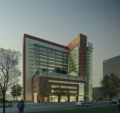
Mercy Medical Center
Replacement Clinical Tower Baltimore,Maryland
| Home |
| About Nicole |
| Building Statistics |
| Thesis Abstract |
| Technical Assignments |
| Thesis Research |
| Thesis Proposal |
| Presentation |
| Final Report |
| Reflection |
| E-Studio |
User Note:Note: While great efforts have been taken to provide accurate and complete information on the pages of CPEP, please be aware that the information contained herewith is considered a work-in-progress for this thesis project. Modifications and changes related to the original building designs and construction methodologies for this senior thesis project are solely the interpretation of Nicole C. Jenkins. Changes and discrepancies in no way imply that the original design contained errors or was flawed. Differing assumptions, code references, requirements, and methodologies have been incorporated into this thesis project; therefore, investigation results may vary from the original design. |
![]()
Building Statistics
Building Name: Mercy Medical Center-Replacement Clinical Tower
Location and City: Baltimore City, Maryland
Building Occupant Name: Mercy Health Services
Function Type:Acute Care
Size: 681,265 sq. ft
# Of Stories above grade: 17 stories not including, 1 sub grade basement level and a mechanical penthouse.
Primary Project Team:
Dates of Construction:
Actual Cost:
Project Delivery Method:
Major National Codes:
Zoning:
Baltimore City Zoning Code, July 25, 2001.
The existing property being considered for the project site has multiple zoning use classifications. Mercy Medical Center’s legal counsel is assisting MMC in their petition to include the hospital as a permitted use on the proposed building site.
The new hospital may be constructed will be Construction type 1B under IBC 2000 based upon proposed use, height and overall area limits (table 2000 IBC) as follows:
Type 1B
Permitted Proposed
Height Unlimited 19 stories
Area Unlimited 681,000 sq. ft +-.
Demolition:
All existing structures are to be removed along with paving, surfacing, and hardscape elements. The existing structures included are the Calvert parking garage, which is to be replaced, and a remaining townhouse on Calvert Street.Areas in the existing hospital will require demolition. Levels G and 1 that will connect the proposed tunnel to the existing structure, will require demolition. Demolition will also be required at level 3(L)‐ bridge connections. All debris will be disposed of off‐site. Excavation will require careful consideration due to the fact that, there is a difference in elevation. The difference in elevation is approximately 30’ from St. Paul Street to Calvert Street. St. Paul Street will need 3 levels of excavation below grade, while Calvert Street will need excavation for 1 level below grade.
Structural:
The structural system is to be a cast‐in‐place reinforce concrete frame. The existing site has a slope downhill from St. Paul Street at the primary entrance to Calvert Street the secondary entrance. The difference in elevation comes to approximately 30’which will be taken into consideration when excavation begins. It has been decided that the St Paul Street shall have 3 levels below the grade while Calvert Street shall have 1 level below grade.
Foundation:
The type of foundation being utilized will most likely be a drilled shaft. The shafts are to be supported on rock (Gneiss), and are designed for an allowable end‐bearing load of 130ksf. The drilled shafts will be between 20 to 60 feet deep.
Structural Framing:
The structural Frame is a reinforced concrete, cast‐in‐place system. The interior columns will be 30” square; the exterior will be 24” square. The columns for the upper levels will be 24” square and the lower levels will be 36” square. The design for the columns will be further developed in the future.
Floor Construction:
The floor will be a one‐way joist and beam system. The joists will be 53” or 66” pan width.
Slab On Grade:
The slab will be 6” thick with waterproofing, and over a 2” mud slab. Underneath that will be welded wire fabric placed on top of a 6” layer of crushed stone and 10 mil thick vapor barrier.
Lateral Load Resisting System.Reinforced load bearing walls will be used to resist lateral wind and seismic loads.
Bridge and Tunnel Connections:
The tower has two proposed bridge connections. One of the bridges will replace an existing bridge connecting a parking garage to the existing hospital. The bridge will be steel framed and simply supported at both ends. The bridge will connect the new tower and the professional Office building. The other bridge will serve as a connection between the new Pleasant Street parking garage and the new tower. This bridge will be free‐standing cast‐in‐place concrete, with a steel‐framed roof. The floors will be steel framed with a 3” composite deck and a 3 ¼” thick structural lightweight concrete topping slab with shear studs, supported by steel beams. The tunnel will be used to connect the new tower to the existing complex. Located on Pleasant Street, the tunnel will be a cast‐in place concrete structure.
Mechanical System:
Proper ventilation within a medical facility is very critical. The various services require that certain areas of the medical center need more ventilation than others. The main concern with ventilation is the prevention of cross contamination between rooms, and the prevention of air‐borne infection spreading. The systems installed must be efficient and possess a long life span, to keep maintenance minimal. The medical center will employ the use of a chilled water system as well as a steam system. The chilled water will be purchased from Comfort Link, who will be responsible for the transport of the water as well as the chilled water piping and the heat exchangers. The contract with Comfort link is still under negotiation. The steam water will be purchased from Trigen, who will be responsible for transport to the building. Cooling devices will be installed to keep the temperature of the water below 140 degrees F, to decrease the amount of condensation before entering the building drainage system. The mechanical rooms are located on the 7th floor of the tower as well as the mechanical penthouse of the tower. There are a total of 23 AHU’s each with capacities ranging from 32,000 CFM to 60,000 CFM. All air handling units will be associated with a return fan, and will be equipped with an economizing control to provide free cooling during appropriate outdoor conditions. The duct work for the building will include medium‐pressure duct work from the AHU’s to the ATU’s. There will be low‐pressure for downstream ductwork, which will distribute air to the various spaces in the hospital. Filtration criteria for various spaces in the hospital vary with their uses. All inpatient areas will require two filter beds, while all labs, administrative areas and food prep areas will require one filter bed.
Fire Suppression:
The building will use both wet standpipe and automatic sprinkler systems. In all areas of the hospital a light hazard wet system will be installed, except for the electrical, mechanical and communication rooms. Sprinkler risers will be installed in the trash chutes and Linen chutes. All standpipe risers will have fire department valves included with them. An electric fire pump will be installed along with dry pipe sprinklers at the loading dock and drop‐off canopies. All elevator machine rooms and electrical rooms will have sprinkler protection. All sprinkler systems will be tied in with a new fire fighters control panel (FFCP).
Fire Safety:
The fire safety system will be linked with the mechanical fire suppression system. The fire system will provide smoke and fire detectors for the entire hospital. The fire system will include the following:
•Speaker/strobe lights shall be ADA complaint.
•Duct smoke detectors in air handling units.
•Area detectors at smoke/fire doors, and corridors.
•Magnetic door holds open in selected areas.
Electrical System:
The illumination levels within the hospital have an effect on the patients stay, and therefore require a detailed analysis, based on the area being occupied. Visual comfort, usage and task complexity are the main focus of the analysis. Areas such as labs, exam rooms and procedure rooms require illumination levels at higher levels, than a patient’s room or a lobby.
The emergency power requirements play an important role in the operation of the hospital. If the normal service of the building were ever interrupted the emergency would be relied on to provide power for the time being. Emergency power will be divided into a Life Safety branch and a critical branch. The life safety will support Egress lighting, exit signs, the fire alarm system, medical gas alarms and the paging system. The critical system will support the illumination for the nurse call system, the telephone equipment and the mechanical equipment.The materials used for the electrical wiring are as follows. Raceways will consist of electrical metallic tubing, with minimum sizing at ¾ inch. For below grade, non‐metallic tubing will be used. 80 PVC for without encasement and 40 PVC for with encasement. The Busway will use aluminum or copper conductors over the entire length. They will be enclosed in non‐ventilated prefabricated steel. The wires and cables will use #12 AWG, with THWN, THWN or XHHW insulation. Conductors will be color coded and labeled.The Utility Company, Baltimore Gas and Electric (BG&E) will provide the normal electrical service to the replacement tower. BG&E will be providing two 400amp 13.2Kv primary feeders to the medical center’s primary switchboard. These are to be incased in concrete and routed internally. The configuration of the switchboard will be medium‐tie‐medium .The 15KV primary switchboard will have bussing at 1200amp, with 600amp medium voltage circuit interrupters for the feeders. Two double ended substations a north substation and south substation will be supplied. Each substation will have two 2000 KVA 13.2KV to 480/277V three phase 4 wire dry type transformers with 4000amp distribution. The electrical system will be a new 480/277V, 3 Phase, 4 Wire Switchgear. The system will mainly be used to feed the new center as well as major mechanical loads and building loads. The dry type transformers will provide 208/120volt power for smaller mechanical loads, building loads, as well as receptacles and lighting.Emergency service will include three 1000Kw natural gas generators. A 750Kw diesel generator will be provided for the life safety systems of the medical center. This portion of the electrical system is essential for a medical facility because, it ensures that in an emergency, operations within the building can continue.
1.Parallel switch gearing will be provided for the three generators.
2.Transfer switches for critical, life safety and equipment components will be located within the penthouse. All transfer switches are separate.
3.Feeders at 480V will be routed from the generator to the emergency distribution system in the electrical room.
Uninterruptable power systems will be provided for the Hospitals IT data server, and all telecommunication rooms. The UPS will be approximately 1500Kva with an input of 480V, and an output of 208/120V three phase.
Lighting:
All energy saving mechanisms will be put into action concerning the lighting system. The lighting will include the use of lamps, and luminaries. The lamps will be fluorescent lamps 3000 degree Kelvin, T5, and T5H0, compact fluorescent. Ballasts for the fluorescent lamps will be low energy, with the capability of using T5, T5HO, and T8 Lamps. The ballasts will have individual fuses. The minimum conductor size will be #12 AWG. Interior luminaires will be fluorescent and HID (High Intensity Discharge) at 120 volts.
Telecommunication Systems:
The telecommunication system will be used throughout the hospital to provide efficient communication, in all parts of the building. The system will consist of a Nurse Call system, voice paging, a TV system, security and a monitoring system. The Nurse Call system will be used to monitor patient’s needs and address any potential problems the patient may be having. The system will have voice communication capability and will include control stations, dome lights and call devices. The system will be network call capable. Audiovisual will be installed in all rooms. Treatment areas will use multiple priority visual call systems.
Senior Thesis | The Pennsylvania State University|Architectural Engineering|AE Lab|NSBE|Research|Contact Nicole
This Page was last updated on Decembert 18, 2007 , By Nicole C. Jenkins and is hosted by the AE Department ©2007